Embarking on the journey of installing solar panels on your home is a powerful commitment to sustainability, energy independence and moving towards a greener future. Yet, between that initial decision and the first burst of power, lies a critical step that ensures your system is safe, efficient, and legally sound: securing an NEC and local-AHJ complaint solar permit plan that is digitally stamped by a state-licensed professional engineer.
Navigating the solar permitting process can feel overwhelming, filled with technical jargon like Article 690, rapid shutdown, and AHJ requirements. This guide breaks down NEC’s essential mandates into clear, actionable steps, clearly stating the key characteristics of a professional, permit-ready solar plan set. By understanding what inspectors look for, you gain the confidence to move your project forward smoothly and safely.
Step 1: Understanding the Code – NEC Article 690 as Your Foundation
The National Electrical Code (NEC) is the benchmark for safe electrical design in the United States. For solar photovoltaic (PV) systems, Article 690 is your indispensable rulebook. Its purpose isn’t to create obstacles but to establish rigorous safety standards that prevent fire and electrical hazards.
Think of Article 690 as your blueprint’s DNA. It governs everything from wire sizing and overcurrent protection to equipment grounding. Ignoring these fundamentals is the fastest path to a permit rejection. A professional solar permit plan takes care of all applicable code regulations in their clear diagrams and specifications, proving to your local building department and utility that the proposed installation won’t compromise your home’s safety.
Step 2: The Non-Negotiable – Rapid Shutdown Requirements (NEC 690.12)
One of the most critical safety innovations in modern solar is the rapid shutdown system. Mandated by NEC 690.12 for roof-mount solar PV systems, this requirement ensures that in case of emergency, first responders (fire fighters etc.) can quickly de-energize high-voltage DC conductors on your roof.
A compliant permit plan must clearly detail this system. This includes specifying listed rapid shutdown equipment (like module-level power electronics or inverters with built-in functionality) and showing the boundary of the controlled conductors on the roof layout. For inspectors, a properly documented rapid shutdown plan is often a top priority, as it directly addresses firefighter safety. Ground-mount systems do not require rapid shutdown requirement.
Step 3: Calculating Your System’s “Nameplate” – The 120% Rule and Point of Interface
Your home’s main electrical service panel has a finite capacity. The NEC’s 120% rule (found in NEC 705.12) is a vital calculation that determines how much solar current can safely backfeed into this panel without overloading it.
In simple words, if a home is equipped with a main service panel of 200A, then according to the 120% rule, the maximum current we can supply to the main service panel is 40A.
A key characteristic of a professional solar permit plan set is a clear load calculation and a dedicated three-line diagram showing the interconnection point. If your system output current exceeds this limit, the plans should propose a compliant solution, such as a line-side tap or a panel upgrade, or main breaker derating.
Step 4: Protecting Against Faults – Grounding, GFCIs, Arc-Fault Protection, and Required Disconnects
The NEC mandates multiple layers of protection against electrical faults, and your plans must document each one.
> Equipment Grounding: All metal parts—racking, enclosures, inverters—must be bonded together and connected to your home’s grounding electrode system. Plans show this via a grounding line in the three-line diagram.
> Arc-Fault Circuit Interruption (AFCI): NEC 690.11 requires AFCI protection for DC PV circuits to detect and interrupt dangerous arc faults that can cause fires. Your plans must specify AFCI-equipped inverters or combiners.
> Ground-Fault Protection (GFPI): This protects against current leakage to ground, a critical safeguard. Many modern inverters integrate this protection, which should be noted on the equipment schedule.
> Critical Disconnect Requirements: Disconnects are vital for safety, allowing your system to be fully de-energized. For most modern systems, an external DC disconnect is not required as this function is integral to the listed inverter in most cases, which must also be indicated on the single-line diagram. However, a fused, lockable AC disconnect is almost always mandatory; this external, accessible switch must be lockable, visible, and accessible, typically installed near the main meter within 10 feet, with its location and specs clearly detailed on the site and electrical plans.
Step 5: Speaking the Local Language – Adhering to AHJ Requirements
The Authority Having Jurisdiction (AHJ)—your city or county building department—has the final say. They enforce NEC or local electric code but often add local amendments or have specific plan formatting requirements. A truly permit-ready plan set is tailored to your AHJ.
This is where ROSEC SOLAR comes in. We don’t just apply the NEC; we research and integrate local AHJ requirements, from unique zoning setbacks to required stamp formats. This local expertise dramatically increases the likelihood of first-pass approval, preventing frustrating cycles of review and revisions.
Key Characteristics of a Professional, Permit-Ready Solar Plan Set
Now that we’ve walked through the major steps, let’s summarize what these requirements look like on paper sheet. A professional solar permit plan set is a PDF documents with different pages covering the following details:
> Site-Specific Roof Plan: A scaled, dimensioned drawing showing exact PV panels, major equipment placement and conduit routing, roof vents, setbacks and obstructions etc.
> Detailed Three-Line (Electrical) Diagram: The heart of the plans, illustrating every major component, wire size, conduit run, overcurrent device, disconnects and applicable NEC notes.
> Equipment Schedule & Specifications: A detailed list of every product (panels, inverters, racking) with make, model, and electrical ratings.
> Professional Engineer Stamp: For most solar PV systems, a Professional Engineer (PE) digital or wet stamp is mandatory on the permit plan to prove your electrical system compliance as per NEC and to prove your roof can handle the weight and wind loads.
> Compliance Documentation: Clear callouts referencing specific NEC code sections (690.12, 705.12, etc.) to guide the inspector’s review.
A Page-by-Page Look at an NEC-Compliant Solar Permit Plan Set
Here’s how ROSEC Solar’s typical solar permit plan set is structured with appropriate details to ensure compliance with various codes and local AHJ regulatory requirements.
Page 1: Cover Sheet
The cover sheet provides an overview of the project and client details, such as system DC and AC size, DC/AC ratio, module and inverter specifications. The cover sheet also indicates the design wind speed and snow load, project address, utility and applicable zoning along with a table of content indicating sheet numbers and titles respectively.
Page 2: Site Plan
The site plan shows typical property layout indicating the nearby roads, driveway, roof layout, solar panels, and major equipment location – meter, service panel(s), inverter(s), AC disconnect etc. The drawing also provides a legend along with a table including the roof/array details, number of modules, total area, roof area, roof percentage coverage etc. along with some other general notes. Moreover, it also clearly indicates the ground and roof access points locations.
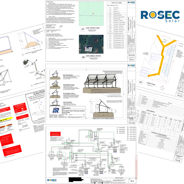
Page 3: Roof Plan
The roof plan contains detailed the PV array layout, roof layout, rafters, roof attachments and their spacing, rails, mid-clamps and end-clamps, string layout along with the roof area and coverage details, attachment and clamp quantity, panel tilt and azimuth etc. It is mandatory to provide a fire setback for firefighters as per regulatory requirements and one or multiple roof access points all the way to the ridge line. If sufficient space is available on both sides of the ridge, it is a common practice to keep 18″ fire setback on both side (making a total of 36″).
Page 4: Racking Details
A sheet providing structural details of the different components of the racking system. Details and drawings of the roof attachments, front-view of the solar array showing maximum attachment spacing, side-view of the array showing attachments, rail, height of panel from roof surface and much more. In case where more details are needed, the racking details page is supported by another page for incorporating the additional drawings. Moreover, structural details are further supported by a table containing details of module make, model and quantity, total module area, racking system technical details, total point load (psf), distributed load (psf), rafter details, attachment quantity etc.
Page 5: Three Line Diagram
The main electrical design indicated in the form of a three line diagram clearly showing the PV module, strings and rapid shutdown devices (if applicable) along with their technical specifications. Details of the PV inverter, batteries, DC and AC disconnects, and system connection (load side or line side) as per NEC are also indicate on the line diagram. The drawing is supported with various comments and references from NEC.
Page 6: Design Calculations & Tables
A sheet containing two major tables. The first one being a BOM table containing all equipment, their quantities and specifications. While second one being the design calculations table showing cable sizing, grounding conductor sizing, conduit size, conduit fill factor, voltage drop, circuit current, cable rating as per NEC 2023, derated current, OCPD sizing etc.
Page 7: Signage & Labels
Safety signs and labels are a critical NEC requirement. This page provides details of the labels themselves as per NEC references – wording, markings, color scheme, physical size in inches and placement location. Some typical labels include general warning and caution labels, PV disconnect label, rapid shutdown label, max voltage and current, battery/ESS labels and so on.
Datasheets and Reports
Lastly, a typical solar permit planset contains datasheets of all equipment from PV module, to inverter, battery, grid boss (or other device if applicable), mounting structure and rails, DC disconnect and so on. The datasheets are followed by typical structural or wind-load reports from manufacturers like IronRidge, S5! or others.
Conclusion: From Confusion to Confidence
Navigating regulatory requirements for residential solar systems can be challenging especially when you are living in the US, but with the right partner, it becomes a seamless process. A well-prepared permit plan set is more than just paperwork—it’s the foundation of a safe, compliant, and efficient solar installation.
The final, most important characteristic of a successful plan set is that it earns your building department and utility permits. Instead of navigating code books and jurisdiction websites, you can partner with an expert. We specializes in delivering permit-ready, NEC-compliant residential solar plan sets and PE stamps within days, giving you the confidence that your project starts on solid, approved ground.
At ROSEC Solar, we take pride in delivering comprehensive, NEC-compliant solar permit plan sets that keep your projects on track. Ready to transform your solar power dream into a permitted reality? Contact us today and let’s get started, read through our FAQs if you have questions in mind or visit our portfolio section to see of some of example solar permit plans.